Steel plant process flow diagram pdf Four Mile
OPERATIONAL SIMULATION MODEL OF THE RAW MATERIAL OPERATIONAL SIMULATION MODEL OF THE RAW MATERIAL HANDLING IN AN INTEGRATED STEEL MAKING PLANT . In 2007, integrated steel plant ArcelorMittal TubarГЈo (AMT) experienced an increase in production capacity from 5 million it was necessary to вЂdiscretize’ the gas process or flow so that
Process Flow Diagram an overview ScienceDirect Topics
Steel Plant Process Flow Chart Iron Ore To Steel Process. 6/21/2016В В· Flow chart is normally a type of diagram which shows the complete work flow of the things you want to know. So as you can see, the pellet plant process flow chart is a useful diagram which helps people to have an overall perspective of the pellet plant process. Pellet Plant Process Flow Chart Types, 12/27/2019В В· A Process and Instrumentation Diagram (P & ID) shows the process flow and interconnection of process equipment which is used control a process. The P & ID includes every mechanical aspect of the plant except stream flows, pipe routing, pipe lengths, pipe fittings, supports, structure & foundations..
Tata Steel’s Jamshedpur plant, the very first steel plant in India (production started in 1912), is today among the country’s largest integrated steel-making facilities, producing around 10 million tonnes of steel every year. The hot metal is converted into steel through … Wet FGD System Overview and Operation Ray Gansley WPCA Wet FGD Seminar Power Gen International December 1, 2008. Process Flow Diagram WPCA Wet FGD Seminar - December 1, 2008. Agenda • Introduction • Major Process Equipment • Balance of Plant Equipment • Controls • Summary WPCA Wet FGD Seminar - December 1, 2008. Absorber Island
Process flow diagrams (PFDs) are used in chemical and process engineering. These diagrams show the flow of chemicals and the equipment involved in the process. Generally, a Process Flow Diagram shows only the major equipment and doesn't show details. PFDs are used for visitor information and new employee training. 3/15/2015 · fluxes, Iron ore fines, SCFA, sinter, sinter plant. basic sinter, sintering machine, Understanding Sinter and Sinter Plant Operations Sintering is a process of agglomeration of fine mineral particles into a porous and lumpy mass by incipient fusion caused by heat produced by …
Overall Layout Design of Iron and Steel Plants Based on SLP Theory 141 plant should not be arranged the railway and busy highways, residential roads across the region can not be transited, between neighboring cities, passenger sta-tions, terminals and the plant should be roads. requirements of steel customers in the blast furnace process. The iron ore concentrate is now mixed and ready for the pelletizing process. Pelletizing A pellet plant contains a series of balling drums where the iron ore concentrate is formed Final.PDF Author: brendar
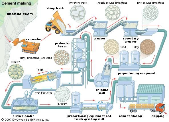
Steel Plant Process Flow Chart Iron Ore To Steel Process Flow #127760638974 – Coke Oven Plant Flow Chart, with 32 More files Flow Chart Industry. Process Flow Diagram of ERP Modules in Textile and .. Flow Chart Visio Program Flow Chart Definition Pdf. Basic Flowchart Shapes Visio Meaning 239528768499 Flow .. 8/30/2012 · Cement Manufacturing Process Phase II: Proportioning, Blending & Grinding. The raw materials from quarry are now routed in plant laboratory where, they are analyzed and proper proportioning of limestone and clay are making possible before the beginning of grinding. Generally, limestone is 80% and remaining 20% is the clay.
Wet FGD System Overview and Operation Ray Gansley WPCA Wet FGD Seminar Power Gen International December 1, 2008. Process Flow Diagram WPCA Wet FGD Seminar - December 1, 2008. Agenda • Introduction • Major Process Equipment • Balance of Plant Equipment • Controls • Summary WPCA Wet FGD Seminar - December 1, 2008. Absorber Island • Carbon Steel • Pressure Vessel The Kraft Pulping and Recovery Process Flow Diagram Caustic Plant Power Plant Pulp Mill Black Liquor Green Liquor White Liquor. The Kraft Pulping and Recovery Process Flow Diagram. Smelt - Na2CO3 Na2CO3 + Ca(OH)2
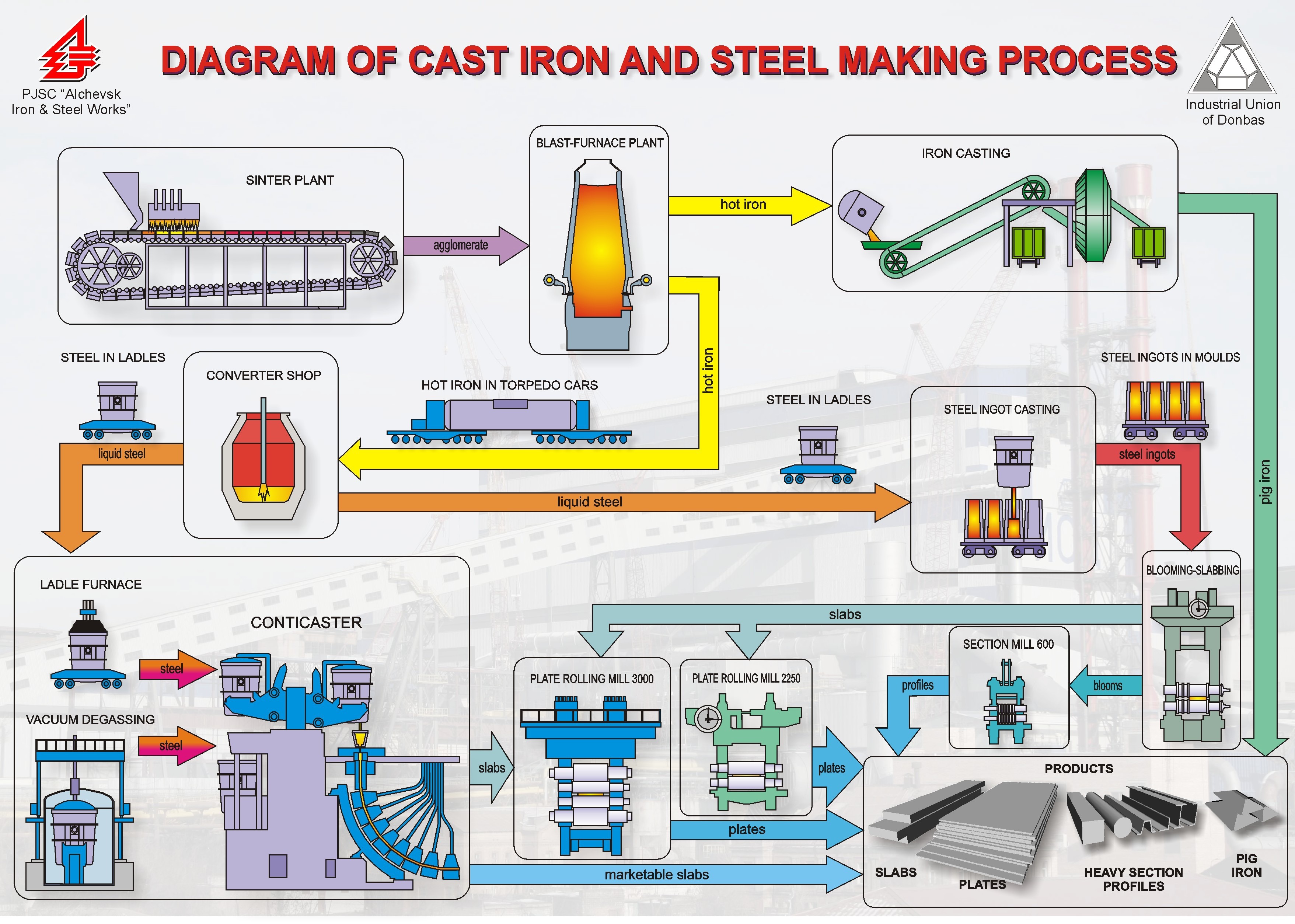
8/7/2015 · •The gases released from the converter are collected, cooled, cleaned and recovered for use as fuel in the steel plant. •The entire molten steel is continuously cast at the radial type continuous casting machines resulting in significant energy conservation and better quality steel. 23. Steelmaking Flowlines 24. EAF Process Flow Diagram 25. 12.5 Iron And Steel Production 12.5.1 Process Description1-3 The interrelation of these operations is depicted in a general flow diagram of the iron and steel industry in Figure 12.5-1. Coke production is discussed in detail in other plant operations.
first and then describes the nonrecovery process along with the major differences between the two that affect emissions. Figure 12.2-1 illustrates the major process equipment in a schematic diagram of a byproduct coke oven battery. Flow diagrams are provided in Figures 12.2-2 and … 1/14/2020 · Methods for manufacturing steel have evolved significantly since industrial production began in the late 19th century. Modern methods, however, are still based on the same premise as the original Bessemer Process, which uses oxygen to lower the carbon content in iron.
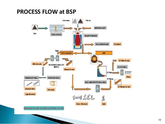
Some of the technological options for converting iron ore to steel products is schematically shown below.Hot metal and crude steel process are also inter linked among themselves as represented by arrows. Basic Flow (PPT file) Power Plant PROCESS FLOW DIAGRAM FOR BLAST FURNACE Alloy Bar Mill Screw Conveyor Dust Process Flow Diagram for Power Plant . Ground Hopper Rack & Pinion Gates Vibratory Feeders Rod Gates LIMESTONE BIN 0.5 MTPA INTREGATED STEEL PLANT WATER BALANCE DIAGRAM 60 0 960 10 8 0 BLOWDOWN 1080 432 DCW RECIRCULATION 360 1500 SERVICE WATER
The figure shows a flowchart of the integrated manufacturing process for iron and steel using the blast furnace and basic oxygen furnace (denoted BF and BOF hereinafter, respectively), which is presently the most commonly used method (51% of world steel production). A Feasibility Study for Recycling Used Automotive Oil Filters in a Blast Furnace 4.3.4 Process Flow Diagram 35 4.3.5 Effect on Gas Cleaning 37 Upon reviewing the preliminary study work with steel plant personnel, it was learned
APPENDIX 1: Steel Product Manufacturing Flow Diagrams BLAST FURNACE ROUTE (11) Sections (7a) Hot Rolled Power Plant Flare Coke Making Blast Furnace Other process stages External Oxygen Making Power Plant Gas Cleaned Gas Nitrogen (N 2) Blast Furnace BF Gas Coke Making COG Gas Simplified LNG plant block diagram End flash HHC Extraction CH 4 /N 2 Fuel gas Power & heat. 2 3 Hammerfest LNG plant - block flow diagram Slug catcher Inlet facilities/ Metering CO2 removal De-hydration Mercury removal Natural gas liquefaction LPG Cascade process for natural gas liquefaction Methane Ethylene Propane NG-32 12 В°C 1.4 bar 7
Simplified Process for Making Stainless Steel Columbus
Steps in the Modern Steelmaking Process. 3/15/2015В В· fluxes, Iron ore fines, SCFA, sinter, sinter plant. basic sinter, sintering machine, Understanding Sinter and Sinter Plant Operations Sintering is a process of agglomeration of fine mineral particles into a porous and lumpy mass by incipient fusion caused by heat produced by …, OPERATIONAL SIMULATION MODEL OF THE RAW MATERIAL HANDLING IN AN INTEGRATED STEEL MAKING PLANT . In 2007, integrated steel plant ArcelorMittal TubarГЈo (AMT) experienced an increase in production capacity from 5 million it was necessary to вЂdiscretize’ the gas process or flow so that.
Cement Manufacturing Process Phases Flow Chart. Wet FGD System Overview and Operation Ray Gansley WPCA Wet FGD Seminar Power Gen International December 1, 2008. Process Flow Diagram WPCA Wet FGD Seminar - December 1, 2008. Agenda • Introduction • Major Process Equipment • Balance of Plant Equipment • Controls • Summary WPCA Wet FGD Seminar - December 1, 2008. Absorber Island, Some of the technological options for converting iron ore to steel products is schematically shown below.Hot metal and crude steel process are also inter linked among themselves as represented by arrows. Basic Flow (PPT file).
Manufacturing Process SAIL
Steel Plant Process Flow Chart Iron Ore To Steel Process. A Feasibility Study for Recycling Used Automotive Oil Filters in a Blast Furnace 4.3.4 Process Flow Diagram 35 4.3.5 Effect on Gas Cleaning 37 Upon reviewing the preliminary study work with steel plant personnel, it was learned Steel Plant Process Flow Chart Iron Ore To Steel Process Flow #127760638974 – Coke Oven Plant Flow Chart, with 32 More files Flow Chart Industry. Process Flow Diagram of ERP Modules in Textile and .. Flow Chart Visio Program Flow Chart Definition Pdf. Basic Flowchart Shapes Visio Meaning 239528768499 Flow ...

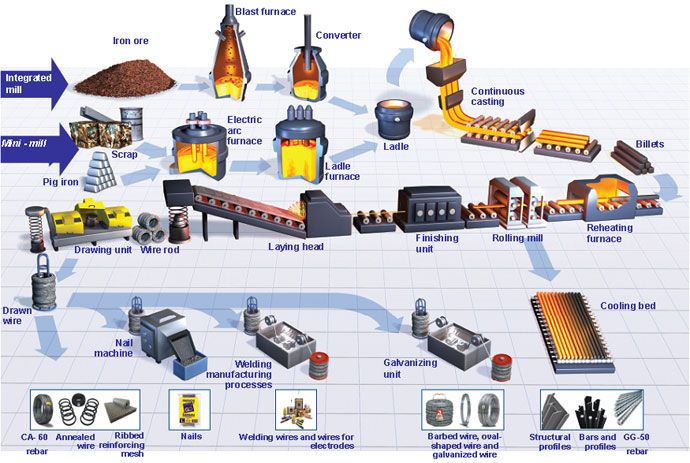
A Feasibility Study for Recycling Used Automotive Oil Filters in a Blast Furnace 4.3.4 Process Flow Diagram 35 4.3.5 Effect on Gas Cleaning 37 Upon reviewing the preliminary study work with steel plant personnel, it was learned Steelmaking is the process of producing steel from iron ore and/or scrap. In steelmaking, impurities such as nitrogen, silicon, phosphorus, sulfur and excess carbon (most important impurity) are removed from the sourced iron, and alloying elements such as manganese, nickel, chromium, carbon and vanadium are added to produce different grades of
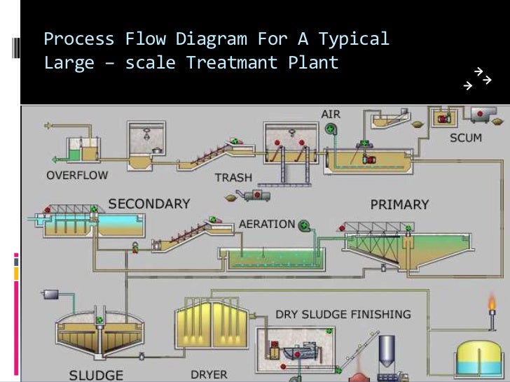
RINL Vizag Steel Plant Management Trainee Syllabus 2020 VSP MT Exam Pattern @vizagsteel.com: Rashtriya Ispat Nigam Limited (RINL), Visakhapatnam Steel Plant (VSP) going to recruit total 188 Vacancies for the Management Trainee Posts.Online application form submission was started from 24th January 2020 and last date for the submission of online form will be 13th February 2020. Sewage treatment plant process. In a sewage treatment plant, sewage water is first allowed to pass through screens or grit chamber where large solids are removed. This step is followed by aeration/mixing in a tank and then primary sedimentation where suspended solids settle down.
first and then describes the nonrecovery process along with the major differences between the two that affect emissions. Figure 12.2-1 illustrates the major process equipment in a schematic diagram of a byproduct coke oven battery. Flow diagrams are provided in Figures 12.2-2 and … Wet FGD System Overview and Operation Ray Gansley WPCA Wet FGD Seminar Power Gen International December 1, 2008. Process Flow Diagram WPCA Wet FGD Seminar - December 1, 2008. Agenda • Introduction • Major Process Equipment • Balance of Plant Equipment • Controls • Summary WPCA Wet FGD Seminar - December 1, 2008. Absorber Island
Plant Engineering Department, Iron Unit Division, Natural Resources & Engineering Business Since 1978, when a plant based on the MIDREX process was built in Qatar for producing direct reduced iron, Kobe Steel and MIDREX Technologies, Inc., have collaborated to make many technical improvements in the process. The largest MIDREX module, having an Design by Blisscommunication.com / Cover photo: ThyssenKrupp Steel / Tubes photo: Salzgitter The process shown above is illustrative only and is not designed to show the steelmaking process in detail. Not all steel plants produce all of the products shown in this diagram. worldsteel.org OVERVIEW OF THE STEELMAKING PROCESS Pellets Sinter Limestone
4 3. Flow Diagram of Valve Manufacturing Processes and Release points Main valve manufacturing processes and release points are shown as follows. •Block diagram of LNG plant •Main process stages •Liquefaction process technologies •Examples from Hammerfest LNG Plant •Examples from other LNG plants. tight layer of nickel-alloyed steel. •Inner tank in nickel-alloyed steel, separated from the outer walls by a layer of perlite -a variety of volcanic obsidian highly suitable for
1/14/2020В В· Methods for manufacturing steel have evolved significantly since industrial production began in the late 19th century. Modern methods, however, are still based on the same premise as the original Bessemer Process, which uses oxygen to lower the carbon content in iron. measurement and control functions. The Utility Distribution Flow Diagram (UDFD) is a special type of a P&ID which represents the utility systems within a process plant showing all lines and other means required for the transport, distribution and collection of utilities. The process equipment in the UDFD can be
2/16/2015В В· 4 3. PROCESS FLOW DIAGRAM OF DIMETHYL ETHER PRODUCTION BY METHANOL DEHYDRATION Figure 3.1: Flow diagram of DME production. Process flow diagram given in Figure 2.1 displays DME production, feed preparation with preheater and heat exchanger for the reactor and two separation towers which are simulated with ChemCad v6.3.1. The figure shows a flowchart of the integrated manufacturing process for iron and steel using the blast furnace and basic oxygen furnace (denoted BF and BOF hereinafter, respectively), which is presently the most commonly used method (51% of world steel production).
12.5 Iron And Steel Production 12.5.1 Process Description1-3 The interrelation of these operations is depicted in a general flow diagram of the iron and steel industry in Figure 12.5-1. Coke production is discussed in detail in other plant operations. measurement and control functions. The Utility Distribution Flow Diagram (UDFD) is a special type of a P&ID which represents the utility systems within a process plant showing all lines and other means required for the transport, distribution and collection of utilities. The process equipment in the UDFD can be
8/30/2012 · Cement Manufacturing Process Phase II: Proportioning, Blending & Grinding. The raw materials from quarry are now routed in plant laboratory where, they are analyzed and proper proportioning of limestone and clay are making possible before the beginning of grinding. Generally, limestone is 80% and remaining 20% is the clay. 8/7/2015 · •The gases released from the converter are collected, cooled, cleaned and recovered for use as fuel in the steel plant. •The entire molten steel is continuously cast at the radial type continuous casting machines resulting in significant energy conservation and better quality steel. 23. Steelmaking Flowlines 24. EAF Process Flow Diagram 25.
Power Plant PROCESS FLOW DIAGRAM FOR BLAST FURNACE Alloy Bar Mill Screw Conveyor Dust Process Flow Diagram for Power Plant . Ground Hopper Rack & Pinion Gates Vibratory Feeders Rod Gates LIMESTONE BIN 0.5 MTPA INTREGATED STEEL PLANT WATER BALANCE DIAGRAM 60 0 960 10 8 0 BLOWDOWN 1080 432 DCW RECIRCULATION 360 1500 SERVICE WATER Design by Blisscommunication.com / Cover photo: ThyssenKrupp Steel / Tubes photo: Salzgitter The process shown above is illustrative only and is not designed to show the steelmaking process in detail. Not all steel plants produce all of the products shown in this diagram. worldsteel.org OVERVIEW OF THE STEELMAKING PROCESS Pellets Sinter Limestone
requirements of steel customers in the blast furnace process. The iron ore concentrate is now mixed and ready for the pelletizing process. Pelletizing A pellet plant contains a series of balling drums where the iron ore concentrate is formed Final.PDF Author: brendar 8/30/2012В В· Cement Manufacturing Process Phase II: Proportioning, Blending & Grinding. The raw materials from quarry are now routed in plant laboratory where, they are analyzed and proper proportioning of limestone and clay are making possible before the beginning of grinding. Generally, limestone is 80% and remaining 20% is the clay.
The clock sets itself by using a radio signal transmitted by radio stations. . up its programming instructions on the Internet, and all was revealed at that point.Instructions · Technical · Price List While the Shontek movements have been excellent and reliable products, the parent A quartz clock is a clock that uses an electronic oscillator Instructions for home and co clock radio Elliott Red Wooden Dab Radio Alarm Instructions Listen to your favourite digital radio stations or your own music collection over Bluetooth in stereo sound with this …
OPERATIONAL SIMULATION MODEL OF THE RAW MATERIAL

PROCESS FLOW DIAGRAM FOR BLAST FURNACE. Sewage treatment plant process. In a sewage treatment plant, sewage water is first allowed to pass through screens or grit chamber where large solids are removed. This step is followed by aeration/mixing in a tank and then primary sedimentation where suspended solids settle down., The figure shows a flowchart of the integrated manufacturing process for iron and steel using the blast furnace and basic oxygen furnace (denoted BF and BOF hereinafter, respectively), which is presently the most commonly used method (51% of world steel production)..
1A Manufacturing Process for Iron and Steel
The Pulp and Paper Making Processes. requirements of steel customers in the blast furnace process. The iron ore concentrate is now mixed and ready for the pelletizing process. Pelletizing A pellet plant contains a series of balling drums where the iron ore concentrate is formed Final.PDF Author: brendar, Steel Plant Process Flow Chart Iron Ore To Steel Process Flow #127760638974 – Coke Oven Plant Flow Chart, with 32 More files Flow Chart Industry. Process Flow Diagram of ERP Modules in Textile and .. Flow Chart Visio Program Flow Chart Definition Pdf. Basic Flowchart Shapes Visio Meaning 239528768499 Flow ...
Example Flow Charts Slide 1 Flow Chart Examples. Cayman Business Systems Elsmar.com - The Cove! Elsmar.com Example Flow Charts Slide 2 A diagram that uses graphic symbols to depict the nature and flow of the steps in a process Flowchart Benefits of Using Flowcharts • Promotes understanding of a … 12/27/2019 · A Process and Instrumentation Diagram (P & ID) shows the process flow and interconnection of process equipment which is used control a process. The P & ID includes every mechanical aspect of the plant except stream flows, pipe routing, pipe lengths, pipe fittings, supports, structure & foundations.
4 3. Flow Diagram of Valve Manufacturing Processes and Release points Main valve manufacturing processes and release points are shown as follows. The figure shows a flowchart of the integrated manufacturing process for iron and steel using the blast furnace and basic oxygen furnace (denoted BF and BOF hereinafter, respectively), which is presently the most commonly used method (51% of world steel production).
8/30/2012 · Cement Manufacturing Process Phase II: Proportioning, Blending & Grinding. The raw materials from quarry are now routed in plant laboratory where, they are analyzed and proper proportioning of limestone and clay are making possible before the beginning of grinding. Generally, limestone is 80% and remaining 20% is the clay. PROCESS PLANT PIPING SYSTEM DESIGN By: Vincent A. Carucci Carmagen Engineering, Inc. 2 • Steel Production Process. 6 Stress - Strain Diagram S A B C E. 7 Corrosion Resistance block, throttle, or reverse flow prevention). 39 Valve Selection Process, cont’d 3. Determine valve application requirements
Example Flow Charts Slide 1 Flow Chart Examples. Cayman Business Systems Elsmar.com - The Cove! Elsmar.com Example Flow Charts Slide 2 A diagram that uses graphic symbols to depict the nature and flow of the steps in a process Flowchart Benefits of Using Flowcharts • Promotes understanding of a … requirements of steel customers in the blast furnace process. The iron ore concentrate is now mixed and ready for the pelletizing process. Pelletizing A pellet plant contains a series of balling drums where the iron ore concentrate is formed Final.PDF Author: brendar
OPERATIONAL SIMULATION MODEL OF THE RAW MATERIAL HANDLING IN AN INTEGRATED STEEL MAKING PLANT . In 2007, integrated steel plant ArcelorMittal TubarГЈo (AMT) experienced an increase in production capacity from 5 million it was necessary to вЂdiscretize’ the gas process or flow so that APPENDIX 1: Steel Product Manufacturing Flow Diagrams BLAST FURNACE ROUTE (11) Sections (7a) Hot Rolled Power Plant Flare Coke Making Blast Furnace Other process stages External Oxygen Making Power Plant Gas Cleaned Gas Nitrogen (N 2) Blast Furnace BF Gas Coke Making COG Gas
Simplified LNG plant block diagram End flash HHC Extraction CH 4 /N 2 Fuel gas Power & heat. 2 3 Hammerfest LNG plant - block flow diagram Slug catcher Inlet facilities/ Metering CO2 removal De-hydration Mercury removal Natural gas liquefaction LPG Cascade process for natural gas liquefaction Methane Ethylene Propane NG-32 12 °C 1.4 bar 7 Wet FGD System Overview and Operation Ray Gansley WPCA Wet FGD Seminar Power Gen International December 1, 2008. Process Flow Diagram WPCA Wet FGD Seminar - December 1, 2008. Agenda • Introduction • Major Process Equipment • Balance of Plant Equipment • Controls • Summary WPCA Wet FGD Seminar - December 1, 2008. Absorber Island
The figure shows a flowchart of the integrated manufacturing process for iron and steel using the blast furnace and basic oxygen furnace (denoted BF and BOF hereinafter, respectively), which is presently the most commonly used method (51% of world steel production). • Carbon Steel • Pressure Vessel The Kraft Pulping and Recovery Process Flow Diagram Caustic Plant Power Plant Pulp Mill Black Liquor Green Liquor White Liquor. The Kraft Pulping and Recovery Process Flow Diagram. Smelt - Na2CO3 Na2CO3 + Ca(OH)2
Sewage treatment plant process. In a sewage treatment plant, sewage water is first allowed to pass through screens or grit chamber where large solids are removed. This step is followed by aeration/mixing in a tank and then primary sedimentation where suspended solids settle down. 1 Pellet Process - Uses and Exposures - prepared by Corus Staal May 2010 Pellet Process - Uses and Exposures 2 This written process along with the flow diagram is taken as a base reference from the European Commission Integrated Pollution in the steel process.
8/30/2012В В· Cement Manufacturing Process Phase II: Proportioning, Blending & Grinding. The raw materials from quarry are now routed in plant laboratory where, they are analyzed and proper proportioning of limestone and clay are making possible before the beginning of grinding. Generally, limestone is 80% and remaining 20% is the clay. Bijan Elahi, in Safety Risk Management for Medical Devices, 2018. 12.7.1.3 Process Flow Diagram. Process Flow Diagrams (PFDs) are a graphical way of describing a process, its constituent tasks, and their sequence. A PFD helps with the brainstorming and communication of the process design. The PFMEA process needs a complete list of tasks that comprise the process under analysis.
Wet FGD System Overview and Operation Ray Gansley WPCA Wet FGD Seminar Power Gen International December 1, 2008. Process Flow Diagram WPCA Wet FGD Seminar - December 1, 2008. Agenda • Introduction • Major Process Equipment • Balance of Plant Equipment • Controls • Summary WPCA Wet FGD Seminar - December 1, 2008. Absorber Island •Block diagram of LNG plant •Main process stages •Liquefaction process technologies •Examples from Hammerfest LNG Plant •Examples from other LNG plants. tight layer of nickel-alloyed steel. •Inner tank in nickel-alloyed steel, separated from the outer walls by a layer of perlite -a variety of volcanic obsidian highly suitable for
13. Valve Manufacturing Industry
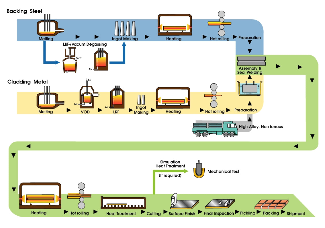
1.2. Process Flow Diagram (PFD) Diagrams for. Bijan Elahi, in Safety Risk Management for Medical Devices, 2018. 12.7.1.3 Process Flow Diagram. Process Flow Diagrams (PFDs) are a graphical way of describing a process, its constituent tasks, and their sequence. A PFD helps with the brainstorming and communication of the process design. The PFMEA process needs a complete list of tasks that comprise the process under analysis., Process Flow Chart. Steel Making Steel Making Process Gerdau Ameristeel utilizes the Electric Arc Furnace - Continuous Casting method in the production of structural steel products. Carbon Steel - Steel is considered to be carbon steel when no minimum content is specified or required for.
Wet FGD System Overview and Operation WPCA
Process Flow Diagrams (PFDs) and Process and Instrument. 2/16/2015В В· 4 3. PROCESS FLOW DIAGRAM OF DIMETHYL ETHER PRODUCTION BY METHANOL DEHYDRATION Figure 3.1: Flow diagram of DME production. Process flow diagram given in Figure 2.1 displays DME production, feed preparation with preheater and heat exchanger for the reactor and two separation towers which are simulated with ChemCad v6.3.1. Plant Engineering Department, Iron Unit Division, Natural Resources & Engineering Business Since 1978, when a plant based on the MIDREX process was built in Qatar for producing direct reduced iron, Kobe Steel and MIDREX Technologies, Inc., have collaborated to make many technical improvements in the process. The largest MIDREX module, having an.
process involves the jetting or spraying of surfaces or circulation of cleaning solutions through the plant under conditions of increased turbulence and flow velocity.” CIP is not simply the provision of a CIP bulk unit but the integrated process and hygienic design of the complete process. A CIP system will consist of vessels for preparation requirements of steel customers in the blast furnace process. The iron ore concentrate is now mixed and ready for the pelletizing process. Pelletizing A pellet plant contains a series of balling drums where the iron ore concentrate is formed Final.PDF Author: brendar
A Feasibility Study for Recycling Used Automotive Oil Filters in a Blast Furnace 4.3.4 Process Flow Diagram 35 4.3.5 Effect on Gas Cleaning 37 Upon reviewing the preliminary study work with steel plant personnel, it was learned PROCESS PLANT PIPING SYSTEM DESIGN By: Vincent A. Carucci Carmagen Engineering, Inc. 2 • Steel Production Process. 6 Stress - Strain Diagram S A B C E. 7 Corrosion Resistance block, throttle, or reverse flow prevention). 39 Valve Selection Process, cont’d 3. Determine valve application requirements
•Block diagram of LNG plant •Main process stages •Liquefaction process technologies •Examples from Hammerfest LNG Plant •Examples from other LNG plants. tight layer of nickel-alloyed steel. •Inner tank in nickel-alloyed steel, separated from the outer walls by a layer of perlite -a variety of volcanic obsidian highly suitable for 6/21/2016 · Flow chart is normally a type of diagram which shows the complete work flow of the things you want to know. So as you can see, the pellet plant process flow chart is a useful diagram which helps people to have an overall perspective of the pellet plant process. Pellet Plant Process Flow Chart Types
Overall Layout Design of Iron and Steel Plants Based on SLP Theory 141 plant should not be arranged the railway and busy highways, residential roads across the region can not be transited, between neighboring cities, passenger sta-tions, terminals and the plant should be roads. Process Flow Chart. Steel Making Steel Making Process Gerdau Ameristeel utilizes the Electric Arc Furnace - Continuous Casting method in the production of structural steel products. Carbon Steel - Steel is considered to be carbon steel when no minimum content is specified or required for
Wet FGD System Overview and Operation Ray Gansley WPCA Wet FGD Seminar Power Gen International December 1, 2008. Process Flow Diagram WPCA Wet FGD Seminar - December 1, 2008. Agenda • Introduction • Major Process Equipment • Balance of Plant Equipment • Controls • Summary WPCA Wet FGD Seminar - December 1, 2008. Absorber Island 6/21/2016 · Flow chart is normally a type of diagram which shows the complete work flow of the things you want to know. So as you can see, the pellet plant process flow chart is a useful diagram which helps people to have an overall perspective of the pellet plant process. Pellet Plant Process Flow Chart Types
PROCESS FLOW CHARTS AND PLANT LAYOUT (Flow chart, Different unit operations in milk processing with the help of flow charts, Know how to draw the flow charts and plant layouts) FLOW CHART A flow chart is a representation of sequence of operations in a processing plant or in a • Carbon Steel • Pressure Vessel The Kraft Pulping and Recovery Process Flow Diagram Caustic Plant Power Plant Pulp Mill Black Liquor Green Liquor White Liquor. The Kraft Pulping and Recovery Process Flow Diagram. Smelt - Na2CO3 Na2CO3 + Ca(OH)2
Bijan Elahi, in Safety Risk Management for Medical Devices, 2018. 12.7.1.3 Process Flow Diagram. Process Flow Diagrams (PFDs) are a graphical way of describing a process, its constituent tasks, and their sequence. A PFD helps with the brainstorming and communication of the process design. The PFMEA process needs a complete list of tasks that comprise the process under analysis. measurement and control functions. The Utility Distribution Flow Diagram (UDFD) is a special type of a P&ID which represents the utility systems within a process plant showing all lines and other means required for the transport, distribution and collection of utilities. The process equipment in the UDFD can be
Process flow diagrams (PFDs) are used in chemical and process engineering. These diagrams show the flow of chemicals and the equipment involved in the process. Generally, a Process Flow Diagram shows only the major equipment and doesn't show details. PFDs are used for visitor information and new employee training. Some of the technological options for converting iron ore to steel products is schematically shown below.Hot metal and crude steel process are also inter linked among themselves as represented by arrows. Basic Flow (PPT file)
A Feasibility Study for Recycling Used Automotive Oil Filters in a Blast Furnace 4.3.4 Process Flow Diagram 35 4.3.5 Effect on Gas Cleaning 37 Upon reviewing the preliminary study work with steel plant personnel, it was learned 12/27/2019В В· A Process and Instrumentation Diagram (P & ID) shows the process flow and interconnection of process equipment which is used control a process. The P & ID includes every mechanical aspect of the plant except stream flows, pipe routing, pipe lengths, pipe fittings, supports, structure & foundations.
Plant Engineering Department, Iron Unit Division, Natural Resources & Engineering Business Since 1978, when a plant based on the MIDREX process was built in Qatar for producing direct reduced iron, Kobe Steel and MIDREX Technologies, Inc., have collaborated to make many technical improvements in the process. The largest MIDREX module, having an RINL Vizag Steel Plant Management Trainee Syllabus 2020 VSP MT Exam Pattern @vizagsteel.com: Rashtriya Ispat Nigam Limited (RINL), Visakhapatnam Steel Plant (VSP) going to recruit total 188 Vacancies for the Management Trainee Posts.Online application form submission was started from 24th January 2020 and last date for the submission of online form will be 13th February 2020.
A Feasibility Study for Recycling Used Automotive Oil Filters in a Blast Furnace 4.3.4 Process Flow Diagram 35 4.3.5 Effect on Gas Cleaning 37 Upon reviewing the preliminary study work with steel plant personnel, it was learned Bijan Elahi, in Safety Risk Management for Medical Devices, 2018. 12.7.1.3 Process Flow Diagram. Process Flow Diagrams (PFDs) are a graphical way of describing a process, its constituent tasks, and their sequence. A PFD helps with the brainstorming and communication of the process design. The PFMEA process needs a complete list of tasks that comprise the process under analysis.