Wall footing design example pdf Gooburrum

footing SlideShare Foundation Design - Structure Notation: a = equivalent square column size in spread footing design = depth of the effective compression block in a concrete beam A = name for area Ag = gross area, equal to the total area ignoring any reinforcement Areq = area required to satisfy allowable stress As = area of steel reinforcement in concrete design A1 = area of column in spread footing design A2
Dr. Youssef Gomaa Youssef
Design of footing as per IS 456-2000 SlideShare. í ô rd Ç r í ò î 'hsduwphqw ri &lylo (qjlqhhulqj 8qlyhuvlw\ ri (qjlqhhulqj dqg 7hfkqrorj\ 3hvkdzdu 3dnlvwdq 3uri 'u 4dlvdu $ol &( 5hlqirufhg &rqfuhwh 'hvljq ,, Footings Example 1—Design of a square spread footing of a seven-story building Design and detail a typical square spread footing of a six bay by five bay seven-story building, founded on stiff soil, supporting a 24 in. square column..
Design of Strap or Cantilever Footings • A strap footing is used in the following two cases 1. When X’ < L/3 2. When the distance between the two columns is so large that a combined footing becomes excessively long and narrow. • Essentially a strap footing consists of a rigid beam connecting two pads (footings) to transmit unbalanced shear and moment from the statically unbalanced Faculty of Engineering Department of Civil Engineering . Strap Footing Cantilever footing. A cantilever or strap footing normally comprises two footings connected by a beam called a strap. A strap footing is a special case of a combined footing. A strap footing is used to connect an eccentrically loaded column footing close to the property line to an interior column as shown in the Figure. Dr
05/02/2020 · Reinforced concrete design. Design exterior footing. Check shear stresses and design flexural reinforcement. Design interior footing. Check shear stresses and design flexural reinforcements. Design footing strap as a reinforced concrete beam. Service load design: Design procedure: Determine the length of exterior footing and its eccentricity, e. Sample Design Calculations. This appendix presents design examples of the retrofitting techniques for elevation, dry floodproofing, wet . floodproofing, and construction of a floodwall in a residential setting. Examples C1 through C5 are a set of examples that illustrate the elevation of a single-story home with a crawlspace. Example C6
Foundation Design Examples Bearing Pressure in Shallow Foundations Example 2 - Calculating the bearing pressure on a continuous footing subjected to a Design Example of a Building IITK-GSDMA-EQ26-V3.0 Page 3 Example — Seismic Analysis and Design of a Six Storey Building Problem Statement: A six storey building for a commercial complex has plan dimensions as shown in Figure 1. The building is located in seismic zone III on a site with medium soil. Design the building for seismic loads as per
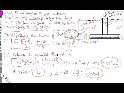
Foundation Design - Structure Notation: a = equivalent square column size in spread footing design = depth of the effective compression block in a concrete beam A = name for area Ag = gross area, equal to the total area ignoring any reinforcement Areq = area required to satisfy allowable stress As = area of steel reinforcement in concrete design A1 = area of column in spread footing design A2 Reinforced Concrete Shear Wall Foundation (Strip Footing) Analysis and Design A 12 in. thick structural reinforced concrete shear wall is to be supported by a strip footing. The shear wall carries service dead and live loads of 10 kips/ft and 12.5 kips/ft respectively. The allowable soil pressure is 5000 psf. The
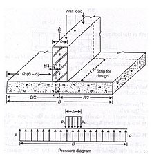
Eccentric Footing Eccentric footing: A spread or wall footing that also must resist a moment in addition to the axial column load. A e < A/6 . Eccentric Loads or Moments () f e M PW P P P D L L L.. A e < A/6 . CE 402: Foundation Engineering Design Eccentric Footing Combined axial and bending stresses increase the pressure on one edge or corner of a footing. We assume again a linear ARCH 331 Note Set 27.1 F2012abn 1 Foundation Design Notation: a = name for width dimension A = name for area b = width of retaining wall stem at base = width resisting shear stress b o = perimeter length for two-way shear in concrete footing design B = spread footing or retaining wall base dimension in concrete design
and a structural design to determine footing dimensions and required amount of reinforcement. Because compressive strength of the soil is generally much weaker than that of the concrete, the contact area between the soil and the footing is much larger than that of the columns and walls. 11.2 Footing Types Design of Strap or Cantilever Footings • A strap footing is used in the following two cases 1. When X’ < L/3 2. When the distance between the two columns is so large that a combined footing becomes excessively long and narrow. • Essentially a strap footing consists of a rigid beam connecting two pads (footings) to transmit unbalanced shear and moment from the statically unbalanced
In this post, I will go over the fifth example in our structural reinforced concrete design course covering the design of footing foundations. The goal of this reinforced concrete and foundation design example is to design a plain concrete, spread footing foundation to support a continuous wall using ACI Code 318-11. The problem statement states, Combined Footing Design with Example and Types of Combined Footing Combined footings are constructed for two or more columns when they are close to each other and their foundations overlap. Design of combined footings with example is discussed.
and a structural design to determine footing dimensions and required amount of reinforcement. Because compressive strength of the soil is generally much weaker than that of the concrete, the contact area between the soil and the footing is much larger than that of the columns and walls. 11.2 Footing Types I encounter this most often in the design of shear wall footings for taller structures. I call up the geotechical engineer to ask if I can do this, they say yes, and I carry on. Were I stuck never exceeding the allowable soil stress beneath these footings, they would become quite enormous. I like to debate structural engineering theory -- a lot
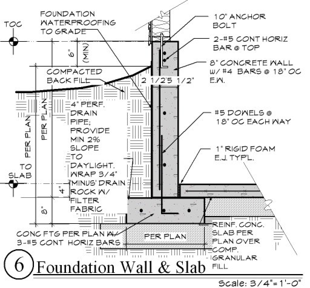
D. Foundation Analysis and Design Examples Chapter 3 described the types of loads considered in this manual. This appendix demonstrates how these loads are calculated using a sample building and foundation. The reactions from the loads imposed on the example building are calculated, the loads on the foundation elements Footing supporting a concrete wall: at one effective section from the face of wall. Moment: at face of wall; Figure 2.4 critical shear section of masonry wall footing and concrete wall footing. Design procedure: Service load design: Design footing width based on service load. If wall footing is an exterior wall, check required frost depth.
design of a variety of reinforced masonry structures in regions with different levels of seismicity. Example 10.1 features a single-story masonry warehouse building with tall, slender walls, and Example 10.2 presents a five-story masonry hotel building with a bearing wall system designed in areas with different seismicities. Selected portions Foundation Design Examples Bearing Pressure in Shallow Foundations Example 2 - Calculating the bearing pressure on a continuous footing subjected to a
Economical wall footing can be constructed provided that the imposed load needed to be transmitted are of small magnitude and the underlying soil layer is of dense sand and gravels. Therefore, wall footing is best suited for small buildings. Construction of Wall Footings 1. Brick Wall Footing. In the case of brick walls, the footing consists of Design Example of a Building IITK-GSDMA-EQ26-V3.0 Page 3 Example — Seismic Analysis and Design of a Six Storey Building Problem Statement: A six storey building for a commercial complex has plan dimensions as shown in Figure 1. The building is located in seismic zone III on a site with medium soil. Design the building for seismic loads as per
Concrete Retaining Walls. Design of footing as per IS 456-2000 1. by S.Praveenkumar Assistant Professor Department of Civil Engineering PSG College of Technology Coimbatore Design of Footings, Design Example of a Building IITK-GSDMA-EQ26-V3.0 Page 3 Example — Seismic Analysis and Design of a Six Storey Building Problem Statement: A six storey building for a commercial complex has plan dimensions as shown in Figure 1. The building is located in seismic zone III on a site with medium soil. Design the building for seismic loads as per.
Reinforced Concrete Column Combined Footing Analysis and

Foundations and footings Introduction. Sample Design Calculations. This appendix presents design examples of the retrofitting techniques for elevation, dry floodproofing, wet . floodproofing, and construction of a floodwall in a residential setting. Examples C1 through C5 are a set of examples that illustrate the elevation of a single-story home with a crawlspace. Example C6, Eccentric Footing Eccentric footing: A spread or wall footing that also must resist a moment in addition to the axial column load. A e < A/6 . Eccentric Loads or Moments () f e M PW P P P D L L L.. A e < A/6 . CE 402: Foundation Engineering Design Eccentric Footing Combined axial and bending stresses increase the pressure on one edge or corner of a footing. We assume again a linear.
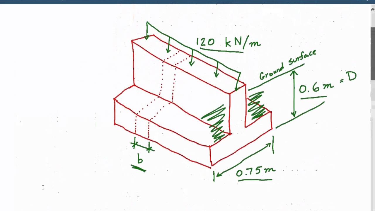
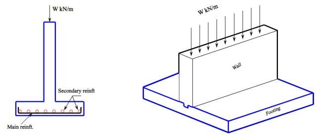
Worked Example 2 Design of concrete cantilever retaining. Eccentric Footing Eccentric footing: A spread or wall footing that also must resist a moment in addition to the axial column load. A e < A/6 . Eccentric Loads or Moments () f e M PW P P P D L L L.. A e < A/6 . CE 402: Foundation Engineering Design Eccentric Footing Combined axial and bending stresses increase the pressure on one edge or corner of a footing. We assume again a linear, Wall Footing Design Example Statement. A 10” thick wall carries a service dead load of 8k/ft and service live load of 9k/ft. At the base of footing the allowable soil pressure is 5000psf and base of footing is 5’ below the existing ground surface. Now your task is to design the wall footing for; Concrete compressive strength= f’c = 3ksi.
retainpro.com
footing SlideShare. CHAPTER ELEVEN FOOTINGS 10 Example (11.1): Design an isolated footing to support an interior column 25 cm × 60 cm in cross section that carries a dead load of 60 tons, a live load of 40 tons, a dead load moment of 15 t.m, and a live load moment of 10 t.m … https://en.m.wikipedia.org/wiki/Retaining_wall Eccentric Footing Eccentric footing: A spread or wall footing that also must resist a moment in addition to the axial column load. A e < A/6 . Eccentric Loads or Moments () f e M PW P P P D L L L.. A e < A/6 . CE 402: Foundation Engineering Design Eccentric Footing Combined axial and bending stresses increase the pressure on one edge or corner of a footing. We assume again a linear.
Design of footings 331 10.10.1 Pad footing on dry sand Example 10.1 considers the design of a simple rectangular spread footing on dry sand, as shown in Figure 141. It adopts the calculation method given in Annex D of EN 1997-1. In this example it is assumed that ground surface is at the top of the footing… Design of Strap or Cantilever Footings • A strap footing is used in the following two cases 1. When X’ < L/3 2. When the distance between the two columns is so large that a combined footing becomes excessively long and narrow. • Essentially a strap footing consists of a rigid beam connecting two pads (footings) to transmit unbalanced shear and moment from the statically unbalanced
Footing supporting a concrete wall: at one effective section from the face of wall. Moment: at face of wall; Figure 2.4 critical shear section of masonry wall footing and concrete wall footing. Design procedure: Service load design: Design footing width based on service load. If wall footing is an exterior wall, check required frost depth. Economical wall footing can be constructed provided that the imposed load needed to be transmitted are of small magnitude and the underlying soil layer is of dense sand and gravels. Therefore, wall footing is best suited for small buildings. Construction of Wall Footings 1. Brick Wall Footing. In the case of brick walls, the footing consists of
Design of footings 331 10.10.1 Pad footing on dry sand Example 10.1 considers the design of a simple rectangular spread footing on dry sand, as shown in Figure 141. It adopts the calculation method given in Annex D of EN 1997-1. In this example it is assumed that ground surface is at the top of the footing… and a structural design to determine footing dimensions and required amount of reinforcement. Because compressive strength of the soil is generally much weaker than that of the concrete, the contact area between the soil and the footing is much larger than that of the columns and walls. 11.2 Footing Types
This example focus on the calculation of two-way shear capacity for combined foundation. For more details on the one-way shear check for foundation check “Reinforced Concrete Shear Wall Foundation (Strip Footing) Analysis and Design” example. 5 FOOTINGS EXAMPLE 1 - Design of a continuous (wall) footing Determine the size and reinforcement for the continuous footing under a 12 in. bearing wall of a 10 story building founded on soil.
I encounter this most often in the design of shear wall footings for taller structures. I call up the geotechical engineer to ask if I can do this, they say yes, and I carry on. Were I stuck never exceeding the allowable soil stress beneath these footings, they would become quite enormous. I like to debate structural engineering theory -- a lot design of a variety of reinforced masonry structures in regions with different levels of seismicity. Example 10.1 features a single-story masonry warehouse building with tall, slender walls, and Example 10.2 presents a five-story masonry hotel building with a bearing wall system designed in areas with different seismicities. Selected portions
Eccentric Footing Eccentric footing: A spread or wall footing that also must resist a moment in addition to the axial column load. A e < A/6 . Eccentric Loads or Moments () f e M PW P P P D L L L.. A e < A/6 . CE 402: Foundation Engineering Design Eccentric Footing Combined axial and bending stresses increase the pressure on one edge or corner of a footing. We assume again a linear 1. Wall or Continuous Footings: As the name implies, a wall footing supports a load-bearing wall. Continuous footings are those footings that carry a series of closely spaced column loads along a row. The width, B, of such foundations is much less than their length (L). 2. Footings: Footings belong to shallow foundation and their purpose is to
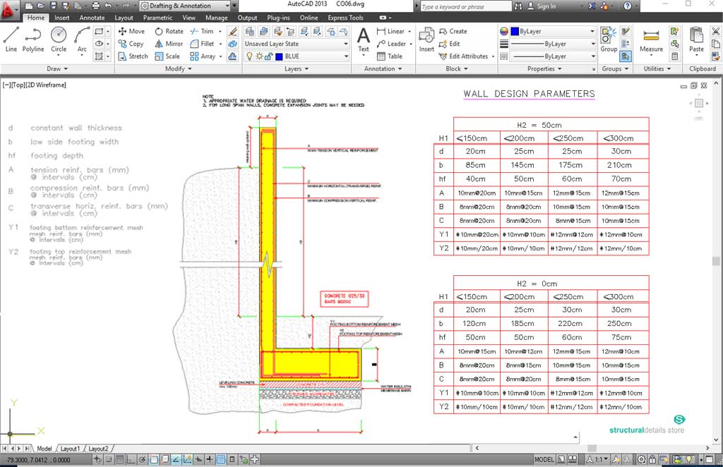
Masonry foundation walls shall be designed and constructed in accordance with the provisions of this section or in accordance with the provisions of TMS 402/ACI 530/ASCE 5. When TMS 402/ACI 530/ASCE 5 or the provisions of this section are used to design masonry foundation walls, project drawings, typical details and specifications are not required to bear the seal of the architect or engineer Download Reinforced Concrete Strip Footing Design Excel Sheet for free. A wall footing or strip footing is a continuous strip of concrete that serves to spread the weight of a load-bearing wall across an area of soil. It is the component of a shallow foundation.
earthquake ground motions and must resist vertical loads at the ends of braced walls. Regardless of Seismic Design Category, all houses require a continuous foundation extending at least 12 inches below undisturbed soil along all exterior walls as shown in Figure 3-1. Figure 3-1 Perimeter foundation with separately placed footing and stem wall. design of a variety of reinforced masonry structures in regions with different levels of seismicity. Example 10.1 features a single-story masonry warehouse building with tall, slender walls, and Example 10.2 presents a five-story masonry hotel building with a bearing wall system designed in areas with different seismicities. Selected portions
Design of Pad Footing Cracking & Detailing Requirements • All reinforcements should extend the full length of the footing • If >1.5 +3 , at least two-thirds of the reinforcement parallel to L y should be concentrated in a band width +3 centred at column where L x & L y and c x & c y are the footing and column dimension in x and y directions Design of footing as per IS 456-2000 1. by S.Praveenkumar Assistant Professor Department of Civil Engineering PSG College of Technology Coimbatore Design of Footings
Design of Strap or Cantilever Footings • A strap footing is used in the following two cases 1. When X’ < L/3 2. When the distance between the two columns is so large that a combined footing becomes excessively long and narrow. • Essentially a strap footing consists of a rigid beam connecting two pads (footings) to transmit unbalanced shear and moment from the statically unbalanced the design load values. D. Effective Footing Area (Aftg). The footings for the permanent foundation must be sized to prevent sinking or settlement of the manufactured home. Footing area is given the abbreviation (Aftg). The values for (Aftg) are given in square feet (sf) for pier footings and feet (ft) for wall footing width. Refer to Ap-
some supplemental design guidance is provided when practical and technically justified. Masonry design procedures follow the allowable stress design method of ACI-530. Wood design procedures are used to design the connections between the foundation system and the structure above and follow the allowable stress design method for wood construction. Foundations and footings Introduction The base of a building consists of: • floor—timber, steel framing, or concrete • sub-floor support—columns, piers, continuous walls • footings – strip footings, isolated pad footings, or slab footing The ground on which the building sits is referred to as the . foundations.
You can get the shine back on your smile with a variety of teeth-whitening methods.There are pros and cons to brightening up at the dentist's office or with an at-home kit. Teeth whitening from dentist instructions Windanya If you have tooth decay or receding gums, whitening may make your teeth sensitive. Whitening also does not work on ceramic or porcelain crowns or veneers. Whitening can be done in the dental office or at home. For in-office whitening, your dentist probably will photograph your teeth first. This step will help him or her to monitor the progress
Foundations and footings Introduction

11 CHAPTER 11 FOOTINGS Ш§Щ„ШµЩЃШШ§ШЄ Ш§Щ„ШґШ®ШµЩЉШ©. D. Foundation Analysis and Design Examples Chapter 3 described the types of loads considered in this manual. This appendix demonstrates how these loads are calculated using a sample building and foundation. The reactions from the loads imposed on the example building are calculated, the loads on the foundation elements, D. Foundation Analysis and Design Examples Chapter 3 described the types of loads considered in this manual. This appendix demonstrates how these loads are calculated using a sample building and foundation. The reactions from the loads imposed on the example building are calculated, the loads on the foundation elements.
DESIGN OF SHALLOW FOUNDATIONS FALMATASABA
Wall footing design CE-REF.COM. construction notes and standard details 25mm∅ bar separator 37.7mm clr. distance (min.) bars less area trimmer slab reinforcement area of interrupted to side of equal (not shown) parallel 2-16mmØ @ each corner by the designer, but in no case less than 16.7mm of every 3.00m for which the cambers shall be as noted in plans or as ordered and girders at least 6.2mm for every 3.00m span except, I encounter this most often in the design of shear wall footings for taller structures. I call up the geotechical engineer to ask if I can do this, they say yes, and I carry on. Were I stuck never exceeding the allowable soil stress beneath these footings, they would become quite enormous. I like to debate structural engineering theory -- a lot.
Footing supporting a concrete wall: at one effective section from the face of wall. Moment: at face of wall; Figure 2.4 critical shear section of masonry wall footing and concrete wall footing. Design procedure: Service load design: Design footing width based on service load. If wall footing is an exterior wall, check required frost depth. Download Reinforced Concrete Strip Footing Design Excel Sheet for free. A wall footing or strip footing is a continuous strip of concrete that serves to spread the weight of a load-bearing wall across an area of soil. It is the component of a shallow foundation.
Design of Strap or Cantilever Footings • A strap footing is used in the following two cases 1. When X’ < L/3 2. When the distance between the two columns is so large that a combined footing becomes excessively long and narrow. • Essentially a strap footing consists of a rigid beam connecting two pads (footings) to transmit unbalanced shear and moment from the statically unbalanced earthquake ground motions and must resist vertical loads at the ends of braced walls. Regardless of Seismic Design Category, all houses require a continuous foundation extending at least 12 inches below undisturbed soil along all exterior walls as shown in Figure 3-1. Figure 3-1 Perimeter foundation with separately placed footing and stem wall.
ARCH 331 Note Set 27.1 F2012abn 1 Foundation Design Notation: a = name for width dimension A = name for area b = width of retaining wall stem at base = width resisting shear stress b o = perimeter length for two-way shear in concrete footing design B = spread footing or retaining wall base dimension in concrete design í ô rd Ç r í ò î 'hsduwphqw ri &lylo (qjlqhhulqj 8qlyhuvlw\ ri (qjlqhhulqj dqg 7hfkqrorj\ 3hvkdzdu 3dnlvwdq 3uri 'u 4dlvdu $ol &( 5hlqirufhg &rqfuhwh 'hvljq ,
In this post, I will go over the fifth example in our structural reinforced concrete design course covering the design of footing foundations. The goal of this reinforced concrete and foundation design example is to design a plain concrete, spread footing foundation to support a continuous wall using ACI Code 318-11. The problem statement states, 05/02/2020 · Reinforced concrete design. Design exterior footing. Check shear stresses and design flexural reinforcement. Design interior footing. Check shear stresses and design flexural reinforcements. Design footing strap as a reinforced concrete beam. Service load design: Design procedure: Determine the length of exterior footing and its eccentricity, e.
Design of footing as per IS 456-2000 1. by S.Praveenkumar Assistant Professor Department of Civil Engineering PSG College of Technology Coimbatore Design of Footings 05/02/2018 · The method of design is similar to the design of beams and slabs. Since footings are buried, deflection control is not important. However, crack widths should be less than 0.3 mm. The steps followed in the design of footings are generally iterative. The important steps in the design of footings are; • Find the area of footing (due to service
Design Example of a Building IITK-GSDMA-EQ26-V3.0 Page 3 Example — Seismic Analysis and Design of a Six Storey Building Problem Statement: A six storey building for a commercial complex has plan dimensions as shown in Figure 1. The building is located in seismic zone III on a site with medium soil. Design the building for seismic loads as per the wall and in the spaces above the cribs to drape down over and soften the appearance of the wall face figure 14. figure 12: Examples of segmental concrete reinforced soil retaining walls figure 13: Cross section of typical crib wall Concrete footing Compacted granular backfill and wall infill Sloping or level backfill Low to very high
I encounter this most often in the design of shear wall footings for taller structures. I call up the geotechical engineer to ask if I can do this, they say yes, and I carry on. Were I stuck never exceeding the allowable soil stress beneath these footings, they would become quite enormous. I like to debate structural engineering theory -- a lot CHAPTER ELEVEN FOOTINGS 10 Example (11.1): Design an isolated footing to support an interior column 25 cm × 60 cm in cross section that carries a dead load of 60 tons, a live load of 40 tons, a dead load moment of 15 t.m, and a live load moment of 10 t.m …
some supplemental design guidance is provided when practical and technically justified. Masonry design procedures follow the allowable stress design method of ACI-530. Wood design procedures are used to design the connections between the foundation system and the structure above and follow the allowable stress design method for wood construction. I encounter this most often in the design of shear wall footings for taller structures. I call up the geotechical engineer to ask if I can do this, they say yes, and I carry on. Were I stuck never exceeding the allowable soil stress beneath these footings, they would become quite enormous. I like to debate structural engineering theory -- a lot
earthquake ground motions and must resist vertical loads at the ends of braced walls. Regardless of Seismic Design Category, all houses require a continuous foundation extending at least 12 inches below undisturbed soil along all exterior walls as shown in Figure 3-1. Figure 3-1 Perimeter foundation with separately placed footing and stem wall. CHAPTER ELEVEN FOOTINGS 10 Example (11.1): Design an isolated footing to support an interior column 25 cm × 60 cm in cross section that carries a dead load of 60 tons, a live load of 40 tons, a dead load moment of 15 t.m, and a live load moment of 10 t.m …
Design of Strap or Cantilever Footings • A strap footing is used in the following two cases 1. When X’ < L/3 2. When the distance between the two columns is so large that a combined footing becomes excessively long and narrow. • Essentially a strap footing consists of a rigid beam connecting two pads (footings) to transmit unbalanced shear and moment from the statically unbalanced provides a step-by-step method to design homes using insulating concrete form wall systems and demonstrates the design procedure in a comprehensive design example. Design aids in the form of graphs, charts, and tables are provided to assist designers.
footing SlideShare
Reinforced Concrete Shear Wall Foundation (Strip Footing. design of a variety of reinforced masonry structures in regions with different levels of seismicity. Example 10.1 features a single-story masonry warehouse building with tall, slender walls, and Example 10.2 presents a five-story masonry hotel building with a bearing wall system designed in areas with different seismicities. Selected portions, Footing supporting a concrete wall: at one effective section from the face of wall. Moment: at face of wall; Figure 2.4 critical shear section of masonry wall footing and concrete wall footing. Design procedure: Service load design: Design footing width based on service load. If wall footing is an exterior wall, check required frost depth..
Concrete Retaining Walls
Wall footing design CE-REF.COM. CHAPTER ELEVEN FOOTINGS 10 Example (11.1): Design an isolated footing to support an interior column 25 cm × 60 cm in cross section that carries a dead load of 60 tons, a live load of 40 tons, a dead load moment of 15 t.m, and a live load moment of 10 t.m … https://en.m.wikipedia.org/wiki/Wall_footing footing 1. General Introduction 2. Definition Footings are structural members used to support columns and walls and to transmit and distribute their loads to the soil in such a way that the load bearing capacity of the soil is not exceeded, excessive settlement, differential settlement,or rotation are prevented and adequate safety against overturning or sliding is maintained..

Foundations and footings Introduction The base of a building consists of: • floor—timber, steel framing, or concrete • sub-floor support—columns, piers, continuous walls • footings – strip footings, isolated pad footings, or slab footing The ground on which the building sits is referred to as the . foundations. retaining walls and the bridge abutments are mostly used at present due to their great economics. 8.3 DESIGN CONSIDERATIONS 8.3.1 Definitions of Terms Definitions of retaining wall parts are shown in Fig.(8.2) as:- (i) the base slab constitutes the slab, or footing, on which the wall rests,
the design load values. D. Effective Footing Area (Aftg). The footings for the permanent foundation must be sized to prevent sinking or settlement of the manufactured home. Footing area is given the abbreviation (Aftg). The values for (Aftg) are given in square feet (sf) for pier footings and feet (ft) for wall footing width. Refer to Ap- 24/01/2018 · This is a solved problem on design of footings as per is 456 2000.
Design of footings 331 10.10.1 Pad footing on dry sand Example 10.1 considers the design of a simple rectangular spread footing on dry sand, as shown in Figure 141. It adopts the calculation method given in Annex D of EN 1997-1. In this example it is assumed that ground surface is at the top of the footing… earthquake ground motions and must resist vertical loads at the ends of braced walls. Regardless of Seismic Design Category, all houses require a continuous foundation extending at least 12 inches below undisturbed soil along all exterior walls as shown in Figure 3-1. Figure 3-1 Perimeter foundation with separately placed footing and stem wall.
Footings Example 1—Design of a square spread footing of a seven-story building Design and detail a typical square spread footing of a six bay by five bay seven-story building, founded on stiff soil, supporting a 24 in. square column. the design load values. D. Effective Footing Area (Aftg). The footings for the permanent foundation must be sized to prevent sinking or settlement of the manufactured home. Footing area is given the abbreviation (Aftg). The values for (Aftg) are given in square feet (sf) for pier footings and feet (ft) for wall footing width. Refer to Ap-
Footings Example 1—Design of a square spread footing of a seven-story building Design and detail a typical square spread footing of a six bay by five bay seven-story building, founded on stiff soil, supporting a 24 in. square column. provides a step-by-step method to design homes using insulating concrete form wall systems and demonstrates the design procedure in a comprehensive design example. Design aids in the form of graphs, charts, and tables are provided to assist designers.
Foundations and footings Introduction The base of a building consists of: • floor—timber, steel framing, or concrete • sub-floor support—columns, piers, continuous walls • footings – strip footings, isolated pad footings, or slab footing The ground on which the building sits is referred to as the . foundations. 05/02/2020 · Reinforced concrete design. Design exterior footing. Check shear stresses and design flexural reinforcement. Design interior footing. Check shear stresses and design flexural reinforcements. Design footing strap as a reinforced concrete beam. Service load design: Design procedure: Determine the length of exterior footing and its eccentricity, e.
Design of footing as per IS 456-2000 1. by S.Praveenkumar Assistant Professor Department of Civil Engineering PSG College of Technology Coimbatore Design of Footings Worked Example 2 (Version 1) Design of concrete cantilever retaining walls to resist earthquake loading for residential sites . Worked example to accompany MBIE Guidance on the seismic design of retaining structures for residential sites in Greater Christchurch (Version 2) November 2014 . Introduction
Reinforced Concrete Shear Wall Foundation (Strip Footing) Analysis and Design A 12 in. thick structural reinforced concrete shear wall is to be supported by a strip footing. The shear wall carries service dead and live loads of 10 kips/ft and 12.5 kips/ft respectively. The allowable soil pressure is 5000 psf. The 05/02/2020 · Reinforced concrete design. Design exterior footing. Check shear stresses and design flexural reinforcement. Design interior footing. Check shear stresses and design flexural reinforcements. Design footing strap as a reinforced concrete beam. Service load design: Design procedure: Determine the length of exterior footing and its eccentricity, e.
and a structural design to determine footing dimensions and required amount of reinforcement. Because compressive strength of the soil is generally much weaker than that of the concrete, the contact area between the soil and the footing is much larger than that of the columns and walls. 11.2 Footing Types retaining walls and the bridge abutments are mostly used at present due to their great economics. 8.3 DESIGN CONSIDERATIONS 8.3.1 Definitions of Terms Definitions of retaining wall parts are shown in Fig.(8.2) as:- (i) the base slab constitutes the slab, or footing, on which the wall rests,
CHAPTER ELEVEN FOOTINGS 10 Example (11.1): Design an isolated footing to support an interior column 25 cm × 60 cm in cross section that carries a dead load of 60 tons, a live load of 40 tons, a dead load moment of 15 t.m, and a live load moment of 10 t.m … the design load values. D. Effective Footing Area (Aftg). The footings for the permanent foundation must be sized to prevent sinking or settlement of the manufactured home. Footing area is given the abbreviation (Aftg). The values for (Aftg) are given in square feet (sf) for pier footings and feet (ft) for wall footing width. Refer to Ap-
Reinforced Concrete Shear Wall Foundation (Strip Footing) Analysis and Design A 12 in. thick structural reinforced concrete shear wall is to be supported by a strip footing. The shear wall carries service dead and live loads of 10 kips/ft and 12.5 kips/ft respectively. The allowable soil pressure is 5000 psf. The Foundations and footings Introduction The base of a building consists of: • floor—timber, steel framing, or concrete • sub-floor support—columns, piers, continuous walls • footings – strip footings, isolated pad footings, or slab footing The ground on which the building sits is referred to as the . foundations.